Some Known Incorrect Statements About Wedge Barriers
Excitement About Wedge Barriers

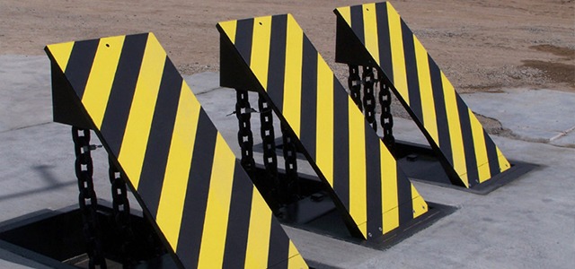
14 and the surface 12 to which the barrier 10 is safeguarded might be made from concrete - Wedge Barriers. 2, the obstacle 10 is mounted to or includes a support or subframe (e. g., support 30 displayed in FIG. 2 )protected beneath the surface 12. The bather 10 might be bolted to the anchor or secured to the support by various other mechanical fasteners. In the illustrated personification, the obstacle 10 consists of a wedge plate 16, which includes a part that is substantially identical with the surface area 12 when the obstacle 10 is in the retracted placement. In various other words, lorries or individuals might overlook the obstacle 10 when the obstacle 10 is in the withdrawed setting and experience mild elevation relative to the surface 12 while on the barrier 10. As gone over carefully listed below, when the obstacle 10 remains in the released position, the wedge plate 16 is held and supported in a raised position by a lifting mechanism of the obstacle 10. Additionally, the parts 18 may be bolted or otherwise mechanically combined to one another. In this way, repair service or substitute of several elements 18 may be streamlined and structured. That is, repair service or substitute of solitary elements
18 might be done more rapidly, quickly, and price efficiently. FIG. In particular embodiments, the support 30 might be a steel framework including plates, light beams(e. g., I-beams ), and/or various other frameworks that are safeguarded within the structure 14, which might be concrete. At the surface area 12, a top side 28 of the anchor 30 may go to the very least partly exposed
, therefore allowing the accessory of the barrier 10 to the anchor 30. g., threaded openings)in several beam of lights or plates of the anchor 30 might be revealed to the surface area 12. In this fashion, bolts 32 or other mechanical bolts may be made use of to protect the barrier 10 to the anchor 30. As the obstacle 10 is placed to the surface 12 of the foundation 14, collection of particles and various other material under the barrier may be lowered, and components of the bather 10 may not be revealed to listed below quality atmospheres. As shown by reference numeral 52, the lifting mechanism 50 consists of elements disposed beneath the wedge plate 16. The parts 52 under the wedge plate 16 may consist of an electromechanical actuator, a webcam, one or more webcam surfaces, and so forth. In addition, the lifting mechanism 50 includes a springtime setting up 54
The springtime pole 58 is combined to a cam(e. g., webcam 80 displayed in FIG. 4) of the lifting system 50. The springs 60 disposed about the spring pole 58 are held in compression by springtime supports 62, including a taken care of springtime assistance 64. That is, the set spring assistance 64 is dealt with about the structure 14 et cetera of the bather 10.
The smart Trick of Wedge Barriers That Nobody is Talking About
The staying force applied to
the cam to deploy release wedge plate 16 may be provided given an electromechanical actuator 84 or other actuator. The springtime setting up 54 and the actuator 84(e. Wedge Barriers. g., electromechanical actuator)might operate together to convert the camera and raise the wedge plate 16.
As discussed above, the springtime assembly 54 puts in a consistent force on the webcam, while the electromechanical actuator might be regulated to exert a variable force on the camera, therefore allowing the lifting and decreasing( i. e., releasing and withdrawing )of the wedge plate 16. In certain embodiments, the continuous force used by the springtime assembly 54 may be adjustable. g., electromechanical actuator) is impaired. As will be valued, the springtime assembly 54 might be covered and safeguarded from particles or other aspects by a cover plate(e. g., cover plate 68 shown in FIG. 4) that might be substantially flush with the elevated surface area 38 of the structure 14. As discussed above, in the released setting, the wedge plate 16 offers to block access or traveling past the obstacle 10. The barrier 10(e. g., the wedge plate 16 )might block pedestrians or automobiles from accessing a property or pathway. As gone over above, the barrier 10 is affixed to the support 30 secured within the structure 14,
front brackets 71. Therefore, the affiliation settings up 72 might pivot and revolve to allow the collapse and expansion of the link settings up 72 throughout retraction and implementation of the bather 10. The linkage settings up 72 reason motion of the wedge plate 16 to be restricted. As an example, if a lorry is taking a trip in the direction of the released wedge plate 16(e. As an example, in one scenario, the security legs 86 may be extended duringupkeep of the obstacle 10. When the security legs 86 are released, the safety and security legs 86 support the weight of the wedge plate 16 against the surface 12. Because of this, the training device 50 may be shut down, serviced, removed, replaced, etc. FIG. 5 is partial perspective sight of an embodiment of the surface-mounted wedge-style obstacle 10, illustrating the webcam 80 and the web cam surface areas 82 of the lifting device 50. Specifically, two webcam surface areas 82, which are referred to as reduced web cam surface areas 83, are positioned listed below the webcam 80. The reduced web cam surface areas 83 may be repaired to the surface 12 (e. For instance, the lower cam surface areas 83 and the installing plate 85 might form a single piece that is safeguarded to the anchor 30 by bolts or other mechanical bolts. In addition, two cam surface areas 82, which are described as top cam surfaces 87, are positioned over the web cam 80 and paired to (e. In various other personifications, intervening layers or plates may be placed in between the surface area 12 and the reduced cam surfaces 83 and/or the wedge plate 16 and the upper webcam surfaces 87 As stated above, the webcam
80 converts along the web cam surfaces 82 when the wedge plate 16 is lifted from the retracted position to the deployed setting. In addition, as mentioned over, the springtime setting up 54 (see Homepage FIG. 3 )might provide a force acting on the webcam 80 in the instructions 102 via springtime pole view website 58, which may reduce the pressure the electromechanical actuator 84 is required to use to the web cam 80 in order to actuate and raise the wedge plate 16. 1 )to the released setting(see FIG. 4). As shown, the cam 80 consists of track wheels 104(e. g., rollers), which get in touch with and equate along the camera surfaces 82 during procedure.